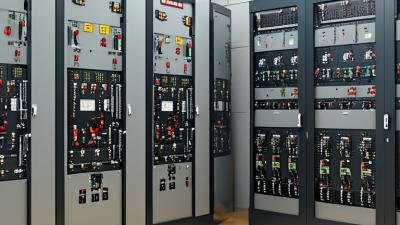
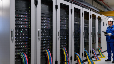
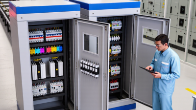
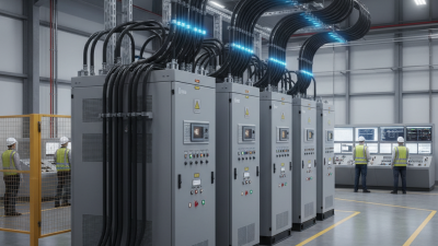
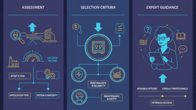
High Voltage Switchgear Series refers to coordinated equipment designed to control, protect, and isolate electrical networks operating at elevated voltages. It commonly includes circuit breakers, disconnectors, earthing switches, busbars, current transformers, voltage transformers, and protective relays. Together, these components manage power flow inside substations, industrial plants, and utility facilities. The arrangement may be air-insulated, gas-insulated, or hybrid, depending on space, climate, maintenance needs, and project specifications.
How does it work? Under normal conditions, the switchgear carries current through firmly supported conductors and busbars. If a fault occurs, sensors detect abnormal current or voltage. A protection relay then sends a trip signal to the circuit breaker. The breaker separates its contacts and interrupts the fault current. Arc-control technology helps extinguish the resulting electrical arc. An earthing switch can then discharge residual energy, allowing trained personnel to inspect the isolated section more safely.
The details matter. A poorly selected interrupting rating can create serious operational risks. Installation quality matters too. Dust, moisture, aging insulation, and incorrect relay settings may reduce reliability. In practice, engineers verify ratings, clearances, interlocking systems, and maintenance records against applicable standards and manufacturer instructions. Field experience also shows that routine testing often reveals problems before failure occurs. Still, no general explanation replaces a site-specific design review. This article introduces the structure and operating logic of the High Voltage Switchgear Series, while recognizing that real systems can behave differently under unusual fault conditions. That limitation deserves attention.
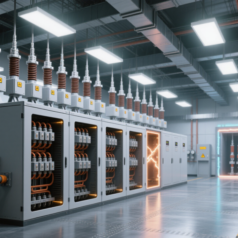
High voltage switchgear series refers to a coordinated range of equipment designed to control, protect, and isolate electrical circuits above 1,000 volts. A typical lineup may include circuit breakers, disconnectors, earthing switches, busbars, instrument transformers, and protective relays. Its purpose is practical: keep power flowing during normal operation and limit damage when faults occur. The word “series” can be confusing. It usually describes compatible units arranged for different voltage levels, current ratings, and site requirements, not one single device.
During operation, a relay monitors current and voltage through instrument transformers. If it detects a short circuit or abnormal load, it sends a trip signal to the circuit breaker. The breaker opens rapidly, separating the faulty section from the energized busbar. Operators can then isolate and ground that section before inspection. Mechanical and electrical interlocks help prevent unsafe switching sequences. In real facilities, small errors in settings or maintenance records can weaken this protection. The hardware may be excellent, but the system still depends on disciplined testing.
Tips: Check rated voltage, continuous current, short-circuit withstand, enclosure class, and environmental conditions before selection. Inspect contact wear, insulation surfaces, relay settings, and grounding connections at scheduled intervals. Keep clear switching procedures near the control panel. Do not rely only on indicator lights; verify isolation with approved test equipment. Even a careful design deserves review after expansion, because new loads can change fault levels and protection coordination.
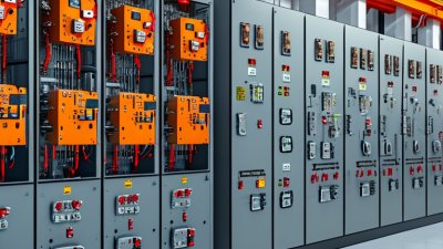
High-voltage switchgear is designed to control, protect, isolate, and safely interrupt electrical circuits. The chart shows selected standard rated voltage levels used for high-voltage switchgear under IEC 62271 voltage-rating conventions.
As rated voltage increases, switchgear generally requires greater insulation distances, stronger dielectric performance, and more advanced interruption and isolation technology.
High voltage switchgear is an engineered assembly that controls, protects, and isolates electrical circuits. Its metal enclosure separates energized parts from operators and surrounding equipment. The circuit breaker is the main switching device. It opens during overloads or short circuits, often within a fraction of a second. During maintenance, a disconnector creates visible electrical separation. It is not normally designed to interrupt heavy fault current. The earthing switch safely connects isolated conductors to ground before work begins. This step matters more than speed.
Busbars distribute incoming power to several feeders inside the switchgear lineup. They must withstand continuous current and short-circuit forces without excessive heating. Current transformers reduce primary current to measurable values. Voltage transformers provide safer voltage signals for meters and protection systems. Protective relays examine these signals and command the breaker to trip when abnormal conditions appear. Control wiring, batteries, and auxiliary contacts support remote operation and status monitoring. Small details count.
Insulating materials, shutters, barriers, and interlocking mechanisms reduce accidental contact. A mechanical interlock can prevent the earthing switch from closing onto a live circuit. Pressure-relief channels may direct internal arc energy away from personnel. Field inspection should check loose connections, moisture, insulation damage, and unusual odors. Testing should follow approved procedures and qualified supervision. A relay setting that works on paper may fail after a system change. That possibility deserves review. In practice, dependable switchgear comes from coordinated protection, careful installation, and disciplined maintenance.
What Is High Voltage Switchgear Series and How Does It Work?
How High Voltage Switchgear Operates Step by Step
High voltage switchgear controls, protects, and isolates electrical circuits in substations and industrial facilities. In normal operation, current passes through a circuit breaker, busbars, and outgoing feeders. Sensors continuously measure current, voltage, and abnormal changes. The control panel stays quiet. That silence usually indicates stable operation, not inactivity.
When a fault occurs, protection relays compare measurements with preset limits. They send a trip signal through the control circuit. The circuit breaker then separates its contacts within milliseconds. An arc appears between the contacts, so the breaker uses an insulating medium to extinguish it safely. The interruption must happen quickly. A delayed response can increase equipment damage and fire risk.
After disconnection, indicators confirm the breaker position, while interlocks prevent unsafe switching sequences. Authorized technicians may isolate the section, verify the absence of voltage, and apply grounding equipment under approved procedures. They inspect relay records before restoring service. This step often reveals problems that visual checks miss. The process sounds straightforward, but real systems are less perfect; sensor errors, weak batteries, or incorrect settings can affect the result. Regular testing, documented maintenance, and competent supervision make the sequence dependable.
| Category / Step | Typical Voltage Class | Main Equipment | How It Works | Typical Technical Data | Primary Purpose |
|---|---|---|---|---|---|
| High-Voltage Switchgear Series | Above 52 kV in common IEC classification practice | Metal-enclosed switchgear, circuit breakers, disconnectors, earthing switches, instrument transformers, surge arresters and protection systems | Combines switching, isolation, measurement, protection and grounding functions within a coordinated substation arrangement. | Rated voltage may include 72.5 kV, 123 kV, 145 kV, 170 kV, 245 kV and higher system levels. | Controls and protects transmission and sub-transmission networks. |
| 1. Normal Energized Condition | System-dependent | Busbars, circuit breaker, disconnectors, current transformers and voltage transformers | Electrical power flows through the closed circuit breaker. Measuring transformers reduce primary current and voltage to levels suitable for meters and protection relays. | Three-phase AC systems; frequency commonly 50 Hz or 60 Hz; insulation coordination is selected for the rated voltage and overvoltage environment. | Maintains continuous power transfer while monitoring system conditions. |
| 2. Fault Detection | System-dependent | Protection relay, current transformer and voltage transformer | The relay analyzes abnormal current, voltage, frequency, impedance or differential quantities and compares them with configured protection settings. | Fault functions can include overcurrent, earth fault, distance, differential, under/overvoltage and breaker-failure protection. | Identifies faults quickly and selects the affected circuit for disconnection. |
| 3. Trip Command | System-dependent | Protection relay, trip circuit, DC control supply and circuit-breaker trip coil | When the protection logic operates, it sends a trip signal to energize the breaker trip coil. The control system normally uses a dependable DC auxiliary supply. | Common control supplies include 48 V, 110 V or 125 V DC, and 220 V or 250 V DC, depending on the installation design. | Initiates rapid isolation of the faulted section. |
| 4. Circuit Breaker Opening | Above 52 kV | SF6, vacuum or other approved high-voltage circuit-breaker technology | The operating mechanism separates the main contacts. The interrupter controls and extinguishes the arc as the AC current approaches a natural current zero. | Rated short-circuit breaking current is commonly specified in kA RMS, with values selected by the network fault level. | Interrupts fault current without allowing unacceptable thermal or mechanical damage. |
| 5. Arc Interruption and Insulation Recovery | Above 52 kV | Interrupter chamber, insulating medium and grading components | After current interruption, the gap between contacts must withstand the transient recovery voltage and prevent the arc from restriking. | Performance is evaluated using power-frequency withstand voltage, lightning impulse withstand voltage and switching impulse withstand voltage where applicable. | Restores electrical insulation between the separated contacts. |
| 6. Circuit Isolation | System-dependent | Disconnector or isolator | After the circuit breaker has opened and current is no longer flowing, the disconnector creates a clearly visible or positively indicated isolation gap. | Disconnectors are generally not intended to interrupt significant load or fault current. | Provides safe electrical separation for inspection, testing and maintenance. |
| 7. Earthing the Isolated Circuit | System-dependent | Earthing switch and substation grounding grid | Once isolation is confirmed, the earthing switch connects the de-energized conductors to earth, discharging trapped or induced voltage. | Earthing-switch short-time withstand ratings are specified in kA for a defined duration, commonly 1 or 3 seconds. | Protects personnel from induced voltage, back-feed and stored electrical energy. |
| 8. Interlocking and Safety Verification | All high-voltage levels | Mechanical interlocks, electrical interlocks, position indicators and control logic | Interlocks prevent unsafe sequences, such as closing an earthing switch onto an energized circuit or operating a disconnector under load. | Design and testing commonly reference IEC 62271 requirements for high-voltage switchgear and controlgear. | Reduces the risk of equipment damage, arc flash and accidental energization. |
| 9. Re-Energization | System-dependent | Protection system, circuit breaker, disconnector and earthing switch | After the fault is cleared and the work permit or operating authorization is complete, the earthing switch opens, the disconnector is positioned correctly and the circuit breaker closes. | Closing may be controlled by synchronism-check, dead-bus or dead-line functions where required by the network design. | Restores service while maintaining system stability and operating safety. |
| Key Standards and Ratings | Applicable to the selected voltage level | Switchgear assembly, breaker, disconnector, earthing switch and insulation system | The equipment is selected and tested according to rated voltage, current, short-circuit capability, insulation level, environmental conditions and operating duty. | Common references include IEC 62271-1 for common specifications, IEC 62271-100 for AC circuit breakers, IEC 62271-102 for disconnectors and earthing switches, and IEC 62271-200 for AC metal-enclosed switchgear up to 52 kV. | Ensures predictable performance, compatibility and safety throughout the switchgear life cycle. |
What Is High Voltage Switchgear Series and How Does It Work?
High-voltage switchgear series control, protect, and isolate electrical circuits above 1,000 volts AC. A circuit breaker interrupts fault current. A disconnector creates visible isolation. An earthing switch safely grounds inactive conductors. Protection relays detect abnormal current, voltage, or frequency, then command the breaker to open. The process is fast, but not always perfect. Incorrect settings can still cause unnecessary outages.
Major Types and Classification of Switchgear Series
Switchgear is commonly classified by voltage, insulation, installation, and construction. Low-voltage equipment operates up to 1 kV. Medium-voltage systems typically cover above 1 kV to about 36 kV, while high-voltage applications exceed that range. Exact boundaries depend on the applicable standard. Air-insulated switchgear uses open air and needs more space. Gas-insulated switchgear is compact, making it useful in dense substations. Vacuum circuit breakers are widely used for medium-voltage switching. Oil-insulated designs remain relevant in some older installations, but maintenance demands careful monitoring. The IEA Electricity 2024 report forecasts global electricity demand growth of about 4% in 2024 and 2025. That expansion increases the need for reliable protection and grid upgrades. Yet market forecasts should be read carefully; definitions and regional coverage differ.
Tips: Check rated voltage, short-circuit withstand, insulation level, and breaking capacity together. Confirm whether the equipment suits indoor or outdoor installation. Review relay coordination with a qualified engineer. A smaller enclosure is not automatically better. Field humidity, dust, altitude, and maintenance access can change the safest choice. Refer to IEC 62271 requirements and local electrical codes before specifying a switchgear series.
High-voltage switchgear series control, protect, and isolate electrical circuits above 1 kV. A typical lineup contains circuit breakers, disconnectors, earthing switches, busbars, current transformers, and protection relays. During a fault, the relay detects abnormal current and commands the breaker to open within milliseconds. The arc is then contained inside a sealed chamber or insulated compartment.
Safety depends on physical separation and disciplined operation. Metal partitions reduce fault propagation, while interlocks can prevent unsafe switching sequences. Arc-resistant enclosures may direct hot gases away from operators. NFPA 70E emphasizes approach boundaries, energized-work controls, and arc-flash risk assessment. PPE remains necessary, even when equipment includes advanced protection. People still make mistakes.
Applications are expanding. The IEA’s Electricity 2024 report estimates data centers used about 460 TWh globally in 2022, with demand potentially exceeding 1,000 TWh by 2026. Reliable switchgear supports data centers, hospitals, factories, renewable-energy plants, and rail systems. Each application needs different short-circuit ratings, voltage levels, and coordination settings.
Maintenance should include visual checks, thermal scanning, insulation testing, contact-resistance measurement, relay testing, and breaker timing analysis. CIGRE guidance stresses condition-based maintenance rather than relying only on fixed intervals. Dust, moisture, loose connections, and repeated switching can quietly increase failure risk. Maintenance records should identify trends, not merely completed tasks. A checklist may still miss hidden insulation damage. That uncomfortable possibility deserves attention.