Leave Your Message

Why Choose Box Type Substation Series for Global Buyers?

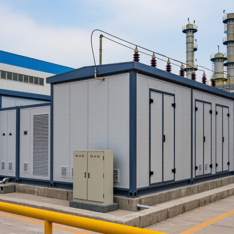
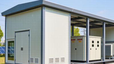
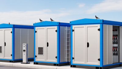
For global power developers, choosing a substation is more than a purchasing decision. It directly affects installation speed, operational safety, and long-term maintenance. The Box Type Substation Series combines a transformer, switchgear, protection devices, and enclosure in one compact unit. This integrated structure can reduce civil work and simplify transportation. On a crowded factory site, that matters. Less space may be required, and fewer field connections can reduce installation risks. However, compact design is not automatically the best solution. Application conditions must guide the selection.

Experienced buyers usually examine transformer capacity, voltage levels, cooling methods, enclosure protection, and maintenance access. They also review short-circuit ratings, grounding arrangements, and monitoring functions. Local climate deserves equal attention. Coastal salt, desert dust, heavy rain, and freezing temperatures can affect enclosure performance. A reliable manufacturer should provide clear drawings, verified test records, material details, and traceable quality controls. Certification requirements also vary between countries, so buyers should confirm applicable grid codes before ordering. Guesswork becomes expensive later.

The strongest choice balances technical performance with practical service support. Suppliers should explain delivery limits, spare-parts availability, commissioning procedures, and warranty responsibilities. Real project experience helps, but every site remains different. A model that performs well in Europe may need adjustment for tropical conditions. This point is easy to overlook. Global buyers should compare documented evidence rather than attractive promises. The Box Type Substation Series can deliver efficient, dependable power distribution when its design matches the network, environment, and regulatory expectations. Careful review remains essential.

Why Choose Box Type Substation Series for Global Buyers?

Box-Type Substations Defined: IEC 62271-202 and Voltage Classes up to 52 kV

Why Choose Box Type Substation Series for Global Buyers?

A box-type substation is a factory-assembled unit containing medium-voltage switchgear, a transformer, and low-voltage distribution equipment. IEC 62271-202:2022 covers prefabricated substations for alternating-current systems above 1 kV and up to 52 kV.

This range includes common classes such as 6.6, 11, 22, 33, 35, 40.5, and 52 kV. Buyers should verify the exact rated voltage, insulation level, frequency, and transformer capacity before ordering.

The standard also addresses enclosure design, temperature rise, dielectric performance, mechanical operation, and routine testing.

In practical inspections, cable compartments, earthing points, and door interlocks deserve close attention. Small design differences affect installation time and maintenance safety. It is not only a metal box.

Weather exposure, dust, humidity, altitude, and local fault levels can change the specification. That part is often underestimated.

The International Energy Agency reported in Electricity Grids and Secure Energy Transitions that annual global grid investment must rise above 600 billion dollars by 2030, from about 400 billion dollars today.

Compact substations can support this expansion where land and construction time are limited. Their factory wiring can reduce site work and improve repeatability.

However, factory assembly does not remove every risk. Transport vibration, ventilation, noise, and future load growth still require engineering review.

IEC compliance is essential, but it is not a substitute for project-specific verification.

Core Ratings Explained: 10–35 kV Medium Voltage, 0.4 kV Low Voltage, 50/60 Hz

Why Choose Box Type Substation Series for Global Buyers?

Core Ratings Explained: 10–35 kV Medium Voltage, 0.4 kV Low Voltage, 50/60 Hz

Box type substations combine medium-voltage switching, transformer capacity, and low-voltage distribution inside a compact enclosure. For global projects, the key range is 10–35 kV on the incoming side. This supports industrial parks, commercial facilities, renewable sites, and utility-connected loads. The low-voltage output is commonly 0.4 kV, suitable for three-phase equipment and building distribution. Always verify the local phase arrangement before approving drawings.

Frequency matters too. Equipment designed for 50 Hz may not suit a 60 Hz network without checking transformer losses, temperature rise, and motor behavior. A 50/60 Hz specification offers useful flexibility, but it does not replace system verification. Rated current must match the transformer’s kVA and the expected demand profile. Oversizing can increase cost and idle losses. Undersizing can create overheating during peak production.

A practical review should examine insulation level, short-circuit withstand, enclosure protection, ventilation, earthing, and cable entry direction. Site altitude and ambient temperature can change thermal performance. Coastal locations may require stronger corrosion protection. Field engineers often find one overlooked detail: the stated voltage is correct, but the protection settings are not coordinated. That mistake deserves attention. A clear test plan, certified components, and documented factory and site testing make the specification more dependable.

Safety by Design: IEC 60529 Enclosures, Arc Protection, and Ground-Fault Control

For global buyers, a box type substation should be judged by protection, not appearance. IEC 60529 enclosures help define resistance against dust and water. The IP rating must match the installation environment. A dusty factory needs different protection from a coastal site with salt spray.

In field inspections, enclosure joints often reveal more than product brochures. Gaskets should sit evenly, doors should close firmly, and cable entries must remain sealed after installation. Small gaps can weaken an otherwise strong enclosure. This detail is easy to overlook.

Arc protection adds another layer of safety. Pressure relief paths, internal barriers, and suitable switching equipment can help limit damage during an internal fault. Ground-fault control is equally important. Proper grounding, residual-current detection, and correctly coordinated protection can reduce dangerous touch voltages and unnecessary outages. Settings should be checked during commissioning, not copied blindly from a standard template.

A certified design is useful. Verified testing is better. Buyers should request enclosure test evidence, arc-fault assessment documents, wiring diagrams, and maintenance instructions. Local conditions still matter. High altitude, temperature changes, and poor ventilation may affect performance. A specification can look complete and still miss a practical risk. Experienced engineers review those gaps before shipment, while installation teams confirm them again on site.

Why Choose Box Type Substation Series for Global Buyers? - Safety by Design: IEC 60529 Enclosures, Arc Protection, and Ground-Fault Control

Safety Dimension Relevant Requirement or Classification Typical Box-Type Substation Design Practical Safety Benefit Buyer Verification Point
Enclosure Protection IEC 60529 ingress protection classification, commonly specified as IP23, IP33, IP43, IP54, or higher depending on the compartment and installation environment. Separate housing for the transformer, medium-voltage switchgear, and low-voltage equipment, with sealed doors, roof drainage, ventilation openings, and protected cable entries. Reduces the risk of accidental contact with hazardous live parts and limits the entry of solid objects, dust, and water according to the selected IP rating. Confirm that the IP rating applies to the complete installed enclosure and that doors, cable glands, ventilation components, and maintenance openings are included in the assessment.
Outdoor Weather Resistance IEC 60529 addresses ingress protection; corrosion protection and environmental durability require additional project specifications and material requirements. Weather-resistant painted steel or corrosion-resistant enclosure materials, sloped roof surfaces, raised cable compartments, and controlled ventilation paths. Helps protect insulation and switching equipment from rain, condensation, airborne pollution, and temperature variation. Check enclosure material, coating system, corrosion category, drainage arrangement, solar loading, ambient temperature range, and local climate requirements.
Internal Arc Protection IEC 62271-200 provides requirements for metal-enclosed AC switchgear and controlgear, including internal arc classification where specified by the purchaser. Pressure-relief ducts or flaps, reinforced compartments, controlled exhaust paths, interlocked doors, and defined personnel protection zones. Directs hot gases and pressure away from operators during a qualifying internal arc event when the assembly is correctly tested and installed. Request the complete internal arc classification, test current, test duration, accessible sides, compartment configuration, and installation conditions.
Medium-Voltage Isolation Switch-disconnector, circuit-breaker, earthing-switch, and interlocking requirements should follow the applicable IEC equipment standard and project specification. Mechanical and electrical interlocks prevent unsafe sequences such as opening an earthing switch onto an energized circuit or accessing compartments before isolation. Supports safe operation, maintenance isolation, and prevention of incorrect switching procedures. Verify the single-line diagram, switching sequence, key or trapped-key interlocking, position indicators, and lockout provisions.
Ground-Fault Detection Ground-fault protection is normally coordinated through residual-current, zero-sequence, or earth-fault measuring functions, according to system grounding and protection design. Core-balance CTs, residual-current transformers, or phase CT residual connections feed an earth-fault relay or circuit-breaker trip unit. Detects current flowing through an unintended ground path and can initiate an alarm or trip before thermal and mechanical damage escalates. Confirm the grounding method, pickup setting, time delay, CT class, sensor placement, trip circuit supervision, and coordination with upstream protection.
Protective Earthing Protective bonding and earthing must comply with the applicable installation rules and the equipment manufacturer’s verified design. Bonded metallic compartments, earth bars, doors connected by flexible bonding conductors, and accessible external earthing terminals. Provides a low-impedance fault path and helps keep exposed conductive parts at a safer potential during an insulation fault. Check earth-bar size, bonding continuity, earth-terminal arrangement, touch-voltage design, and the site earth-grid resistance target.
Transformer Fire and Thermal Safety Transformer selection and installation should reflect the applicable transformer standard, local fire code, ventilation requirements, and risk assessment. Dedicated transformer compartment, temperature monitoring, overload protection, pressure or gas protection where applicable, and fire separation measures based on transformer type. Limits overheating and helps prevent a transformer fault from spreading to adjacent switchgear or control compartments. Confirm transformer type, rated power, cooling method, temperature-rise limits, fire clearances, oil containment requirements, and alarm/trip settings.
Cable Entry and Termination Cable systems must be selected for the rated voltage, insulation level, fault current, environmental conditions, and required bending radius. Dedicated cable chambers with gland plates, screened-cable termination space, phase identification, barriers, and sealed unused entries. Reduces the likelihood of moisture ingress, incorrect phase connections, insulation damage, and accidental contact during maintenance. Verify cable size range, termination type, screen-earthing method, gland compatibility, bend radius, access clearance, and sealing performance.
Low-Voltage Overcurrent Protection Low-voltage circuit-breakers and protective devices should be selected for the calculated load current, prospective short-circuit current, and coordination study. Incoming air or molded-case circuit-breaker, outgoing feeder protection, adjustable thermal-magnetic or electronic trip functions, and visible status indication. Provides overload and short-circuit protection for transformers, busbars, cables, and downstream loads. Check rated current, service short-circuit breaking capacity, selectivity, back-up protection, neutral protection, and trip-unit settings.
Arc-Flash Risk Reduction Arc-flash risk depends on system voltage, available fault current, clearing time, working distance, enclosure configuration, and operating procedures. Fast fault clearing, current-limiting devices where suitable, segregated compartments, remote operation options, shutters, and restricted access during energized work. Can reduce incident energy and operator exposure when supported by a site-specific arc-flash study and validated protection settings. Request calculated incident energy, arc duration, equipment boundary, PPE level, maintenance mode functions, and assumptions used in the study.
Verification and Testing Routine and design verification should be completed in accordance with the applicable IEC product standards and the agreed project inspection plan. Insulation resistance checks, dielectric tests, wiring verification, mechanical operation checks, protection relay testing, earth-continuity checks, and functional interlock tests. Confirms that the assembled substation operates as designed before shipment, energization, and handover. Obtain inspection and test records, calibration certificates, protection-setting sheets, wiring diagrams, and documentation for any type or design tests.
Operational Accessibility Access arrangements should be based on safe working procedures, equipment clearances, local electrical codes, and the manufacturer’s maintenance instructions. Clearly marked operating handles, mimic diagrams, danger labels, compartment separation, lifting points, service lighting provisions, and defined maintenance access. Improves safe inspection, switching, troubleshooting, and replacement of components without unnecessary exposure to energized parts. Review access-side requirements, minimum working clearances, door swing, lifting route, maintenance space, signage language, and emergency isolation provisions.
Global Project Adaptability Final compliance depends on the destination country’s grid parameters, electrical codes, climate, utility rules, and certification requirements. Configurable rated voltage, frequency, transformer connection group, earthing arrangement, protection functions, metering, communications, and cable-entry layout. Allows the same box-type substation concept to be adapted to different network and site conditions without compromising the verified safety design. Confirm rated voltage and frequency, insulation level, short-circuit withstand, utility interface, local certification, language requirements, and site acceptance criteria.

Efficiency and Lifecycle Cost: Transformer Loss Limits Under IEC 60076-20

Why Choose Box Type Substation Series for Global Buyers?

For global buyers, a box type substation combines the transformer, enclosure, switchgear, and protection equipment. This compact arrangement reduces installation work and site interfaces. However, purchase price alone can hide long-term energy costs. Transformer losses continue every hour, even when the load changes. IEC 60076-20 provides a technical framework for evaluating transformer energy efficiency and loss performance. It should be read with the project specification and applicable national efficiency requirements.

During procurement, request guaranteed no-load and load-loss values at defined temperatures and tapping positions. No-load losses matter throughout energised operation. Load losses increase with current, often becoming significant during industrial peaks. A serious comparison should use the buyer’s actual load curve, not only the rated capacity. Factory test records, temperature corrections, and traceable measurement methods improve confidence. In practice, small design compromises may appear acceptable. They can become expensive over twenty years. Yet calculated savings may also disappoint if the assumed load profile is unrealistic.

Tips: Ask for a lifecycle-cost model showing purchase price, losses, maintenance, and expected operating hours. Confirm enclosure ventilation, ambient temperature, altitude, and future load growth. Review the test standard carefully. A cheaper unit is not automatically efficient, and a larger transformer is not automatically better. Leave room for technical doubt. That usually improves the final decision.

Global Purchasing Checklist: IEC, IEEE, Climate, Altitude, and Grid-Code Compliance

Why Choose Box Type Substation Series for Global Buyers?

Global Purchasing Checklist: IEC, IEEE, Climate, Altitude, and Grid-Code Compliance

A box type substation must fit the destination grid, not just the project drawing. Check IEC 62271 for switchgear and IEC 60076 for transformers. Where required, compare IEEE C37 requirements with local utility rules. Ask for type-test reports, routine-test records, short-circuit data, and clear protection settings. A certificate alone may not prove suitability.

Climate conditions need precise attention. Review ambient temperature, humidity, solar radiation, dust, salt fog, and flooding risk. An enclosure rated for ordinary indoor conditions may fail near a coastline. Confirm the IP rating, corrosion protection, ventilation method, and temperature-rise limits. These details affect insulation life and maintenance access.

Altitude is another common procurement gap. Above roughly 1,000 metres, air insulation and cooling performance can change. Request corrected clearances, derating calculations, and transformer thermal data. Grid-code checks should cover grounding, fault levels, relay coordination, voltage variation, frequency limits, and remote monitoring. Local approval may also require specific metering or communication protocols. Do not rely on generic drawings. A careful review compares the substation with the actual site, feeder, and utility interface. Some project teams discover this too late. That mistake is expensive.