Leave Your Message

What Are the Different Types of Transformers?

Transformer Types are easier to understand when viewed through the jobs they perform. A transformer may raise or lower voltage, isolate a circuit, or provide measurements for protective equipment. Michael Faraday’s experiments with electromagnetic induction helped establish the principles behind transformer operation. He famously wrote, “Nothing is too wonderful to be true, if it be consistent with the laws of nature.” That curiosity still matters when comparing real equipment.

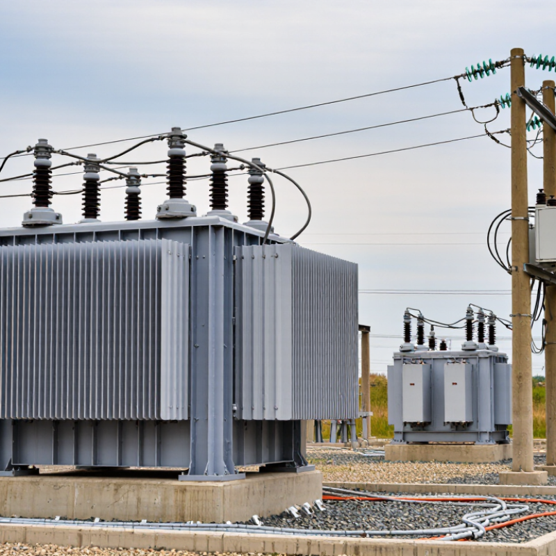
This guide introduces power, distribution, instrument, isolation, and autotransformers. It also considers construction choices, including oil-immersed and dry-type designs. Picture a substation transformer beside a row of compact units mounted on utility poles. Both transfer electrical energy, yet their ratings, cooling systems, and operating environments differ. A current transformer, by contrast, helps monitoring equipment measure a high-current line safely. Different duties. Different designs.

The categories are useful, but they are not perfectly tidy. Some units combine characteristics, and naming conventions can vary by industry or region. A transformer’s label alone cannot confirm that it suits a particular installation. Readers should also examine voltage, capacity, insulation, cooling, and application-specific requirements, then consult qualified engineering guidance for project decisions. This overview is a starting point, not a substitute for a design review. Small details can matter more than expected.
What Are the Different Types of Transformers?

Transformer Classification by Core Construction

Transformer core construction affects the magnetic path, winding arrangement, cooling, and leakage. In a core-type transformer, windings surround the core limbs, often divided between two limbs. This layout can make insulation and servicing more accessible in some designs. A shell-type transformer places its windings around a central limb, with the core surrounding them. The structure can provide strong mechanical support and reduce leakage flux, but winding access may be less convenient.

Neither construction is automatically better. Designers weigh voltage, current, heat, fault forces, and installation space. Many power transformers use laminated electrical steel to limit eddy-current losses. Ferrite cores are common at higher frequencies because they can reduce core losses. Toroidal cores use a continuous ring-shaped magnetic path and can be compact, with low stray fields. Their winding process can be more difficult. Real installations matter: noise, cooling, and maintenance access may change the practical choice.

Tips: Check technical drawings before identifying a core type. The outer casing can be misleading. When selecting a replacement, compare electrical ratings and cooling requirements, not just the core’s shape.

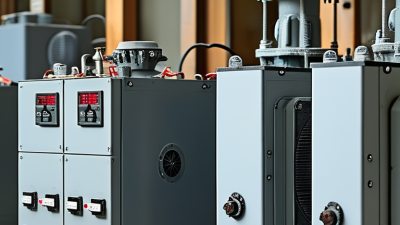
Types Based on Voltage Conversion and Winding Design

Transformers can be grouped by how they change voltage. A step-up transformer produces a higher secondary voltage than its primary voltage, while a step-down transformer produces a lower one. The turns ratio sets this relationship. For example, a 240-to-24 V unit reduces voltage for a compatible low-voltage circuit. An isolation transformer may keep the voltage nearly unchanged while separating its input and output windings electrically. Different purpose.

Winding design adds another useful distinction. A conventional two-winding transformer has separate primary and secondary coils. An autotransformer uses one winding with a shared section, which can make it smaller for some applications. However, its input and output are electrically connected, unlike those of an isolation transformer. Core-type and shell-type designs describe how the core surrounds or sits beside the windings; they do not, by themselves, tell you whether voltage rises or falls. That distinction is easy to miss.

In practice, the right type depends on more than the voltage printed on a label. Check the load, frequency, insulation rating, and expected temperature rise. A motor’s starting current, for instance, may exceed its normal running current and affect transformer sizing. Not always obvious. I’d also avoid treating “step-down” as a complete safety description: the actual installation and protective equipment still matter. Real conditions can be messier than a simple turns-ratio calculation.

Transformers Classified by Phase and Power Capacity

Transformers are commonly classified by phase and power capacity. A single-phase unit suits modest loads, such as a rural home or a small workshop. Three-phase units serve factories, commercial buildings, and substations where motors and heavier loads need balanced power. The phase choice affects connection design and load handling, not simply the transformer's physical size.

Capacity is usually stated in kilovolt-amperes (kVA). Small single-phase distribution units may range from a few kVA to about 167 kVA; three-phase distribution units can extend into the thousands. These are practical examples, not universal boundaries: ratings and category names vary by utility and standard. The U.S. Department of Energy’s 2013 distribution-transformer standards analysis projected 3.49 quadrillion Btu in energy savings over 30 years, underscoring why capacity selection and operating losses matter. IEC 60076 provides a widely used technical framework for transformer ratings and performance. Still, a nameplate rating alone cannot show how a unit will behave under a changing daily load.

Tips: Match phase to the supply and equipment, then size for measured peak demand—not guesswork. Leave headroom, but avoid oversizing without a load study. A little caution helps.

Special-Purpose Transformers and Their Applications

Special-purpose transformers solve problems that ordinary voltage conversion cannot. Current and voltage transformers scale high-voltage signals for meters and protective relays. A current transformer surrounds a cable inside a substation; its output lets equipment detect faults without directly measuring the full line current. Isolation transformers separate circuits, while rectifier transformers supply the controlled power used in electrolysis and industrial drives. Arc-furnace transformers handle intense, rapidly changing loads in steelmaking. They need robust insulation and cooling.

Transport systems use traction transformers to adapt power for trains, while grounding transformers create a neutral point where one is otherwise unavailable. Phase-shifting units can redirect power between transmission paths. These are not interchangeable tools. Selection depends on load profile, insulation level, cooling method, and the consequences of failure. In practice, a small specification mismatch can become a costly site problem.

The International Energy Agency’s 2023 report, Electricity Grids and Secure Energy Transitions, estimates that over 80 million kilometres of grids must be added or refurbished by 2040. It also says annual grid investment needs to rise from about $300 billion to over $600 billion by 2030. Those figures describe the wider grid, not transformer demand alone, but they show why specialist equipment matters. Engineers still need project-specific studies; broad forecasts cannot predict every local constraint. Sometimes, the simplest option is not the safest one.

What Are the Different Types of Transformers? - Special-Purpose Transformers and Their Applications

Transformer Type Primary Function Typical Applications Key Design Consideration
Current transformer (CT) Produces a reduced current proportional to the current in a power circuit for measurement or protection. Metering panels, switchgear, and protective relays in electrical substations and industrial facilities. The secondary circuit must not be left open while the primary is energized, as dangerous voltage may develop.
Voltage transformer (VT/PT) Steps down system voltage to a standardized, safer level for measurement and protection. Voltage monitoring, revenue metering, and relay circuits in high-voltage networks. Accuracy, insulation level, and appropriate protection against secondary-side faults are important.
Isolation transformer Provides electrical separation between input and output circuits, typically with a one-to-one winding ratio. Medical and laboratory equipment, maintenance workbenches, and circuits requiring galvanic isolation. Isolation does not by itself make a circuit safe; grounding and protection must suit the installation.
Autotransformer Changes voltage using a shared winding, often with adjustable taps or a movable contact. Motor starting, voltage adjustment, and interconnection of systems with similar voltage levels. Input and output are electrically connected, so it does not provide galvanic isolation.
Grounding (earthing) transformer Creates a neutral point or grounding path in a system that otherwise lacks one. Three-phase networks with ungrounded or delta-connected sources, including renewable-energy collector systems. Its winding configuration and short-time fault-current rating must match the network grounding design.
Furnace transformer Supplies the low voltage and very high current required by electric furnaces. Electric arc furnaces and other industrial metal-melting processes. Designed to withstand demanding duty cycles, high currents, and changing electrical loads.
Rectifier transformer Feeds a rectifier system and may provide voltage transformation, phase shifting, or electrical isolation. Industrial DC drives, electrolysis, large battery-charging systems, and high-power conversion equipment. Harmonic currents and thermal loading from the rectifier must be considered in the transformer design.
Traction transformer Supplies or converts power for railway traction systems. Electric locomotives, rail substations, and onboard railway power systems. Must suit the railway supply arrangement and withstand vibration, load variation, and demanding operating conditions.
Phase-shifting transformer Adjusts the phase angle between input and output voltages to influence real-power flow. Transmission networks where operators need to manage power sharing between parallel lines. Control range, system stability, and coordination with network protection are key considerations.
Scott-T transformer Connects three-phase and two-phase systems using a pair of specially connected single-phase transformers. Applications requiring a two-phase supply from a three-phase network, or the reverse. Load balance depends on the connected two-phase loads and the correct transformer connections.
Voltage-regulating transformer Adjusts its turns ratio, often under load, to help maintain the required output voltage. Distribution feeders and substations where voltage changes with load or supply conditions. Tap range, operating frequency, switching duty, and coordination with system voltage controls must be considered.

How Operating Conditions Distinguish Transformer Types

Transformer types are easiest to distinguish by the conditions they must handle, not by appearance alone. A neighborhood distribution unit faces changing demand, outdoor weather, and long operating hours. A factory unit may encounter heat, dust, vibration, or repeated motor starts. These conditions influence insulation, cooling, enclosure design, and rated capacity. The nameplate helps, but it cannot capture every installation detail.

Distribution transformers reduce voltage near homes and businesses, often under loads that rise and fall through the day. Power transformers serve substations and larger networks, where sustained high voltage and bulk energy transfer shape their design. Dry-type transformers use air and solid insulation, making them common indoors. Oil-immersed units move heat effectively and often suit outdoor or higher-capacity service. That matters. Neither type is automatically the better choice; ventilation, fire planning, and maintenance all count.

Other designs address specific operating needs. Isolation transformers separate circuits electrically, while autotransformers share a winding and can be more compact, but do not provide that separation. Current and voltage transformers let equipment measure high-current or high-voltage circuits safely. Engineers also consider frequency, waveform, ambient temperature, and altitude. Harmonics can increase heating, and a hot room may reduce usable capacity. One detail is easy to underestimate: actual load patterns can differ from early estimates, so selection deserves careful review.

What Are the Different Types of Transformers? — How Operating Conditions Distinguish Transformer Types

Transformer designs must suit their operating conditions, including heat. Insulation thermal class is one factor used in that design: higher class temperatures indicate insulation systems intended to withstand higher thermal conditions. Actual allowable operating temperatures depend on the transformer design, applicable standards, and loading.

Values shown are the nominal temperatures associated with insulation thermal classes A, E, B, F, and H in IEC 60085. They are class ratings, not universal operating-temperature limits for complete transformers.