What Are the Different Types of Transformers?
A transformer may be small enough to sit beside a doorbell or large enough to hum behind a fenced substation. Both use electromagnetic induction, yet their designs and duties differ. The Types Of Transformers guide begins with that practical distinction: what the device does, where it operates, and what loads it serves. Michael Faraday, whose induction experiments helped establish the science behind transformers, wrote, “I have at last succeeded in exciting a current of electricity by magnetism, and have thereby demonstrated the production of electricity from magnetism.” His 1831 observation points to the principle behind devices that transfer electrical energy between circuits.
The sections ahead compare power, distribution, isolation, instrument, and autotransformers, along with common single-phase and three-phase designs. They explain how voltage levels, winding arrangements, cooling methods, and installation settings shape each type’s use. For example, a distribution transformer on a neighborhood pole has a different job from a current transformer monitoring equipment inside a switchgear cabinet. The categories are not perfectly tidy. A single unit can fit more than one classification, depending on whether it is grouped by function, construction, or application. That overlap can be confusing, and it deserves a closer look rather than a neat but misleading label. This overview offers a practical starting point for recognizing the main designs and understanding why choosing the right one depends on the electrical system around it.
Classify Transformers by Function: Power, Distribution, and Instrument Units
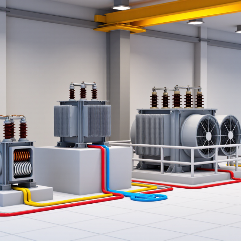
Transformers are commonly classified by their role in the electrical system. Power transformers transfer energy between high-voltage networks, often at generating stations and transmission substations. They handle large loads and are designed around expected operating conditions. Some units stand outdoors in contained yards, with radiators that help carry heat away. Their exact ratings and cooling methods depend on the installation.
Distribution transformers step voltage down for local use in homes, shops, and other buildings. You may see one on a utility pole or inside a street-level enclosure. Instrument transformers serve a different purpose: current transformers and voltage transformers provide scaled signals for meters and protective relays. They help equipment monitor high-energy circuits safely. That matters. Similar-looking units can have different duties, so appearance alone is not a reliable guide.
Tips: Check the nameplate for voltage, rating, and intended use before identifying a unit. Installation details matter, too; a distribution transformer’s location does not tell you its full specifications. If a label is unclear, verify the information with qualified electrical personnel rather than guessing. A small distinction can affect how a system is monitored or supplied.
Compare Single-Phase and Three-Phase Designs on 50 Hz and 60 Hz Grids
Single-phase and three-phase transformers serve different load patterns; grid frequency is a separate design constraint. A small workshop or home circuit may use a single-phase unit. Its construction is simpler, and its output suits many modest loads. Three-phase designs supply balanced power to motors, pumps, and larger facilities. They can use one three-phase transformer or a bank of three single-phase units. The choice affects installation, maintenance, and replacement planning.
Frequency matters because core flux depends on voltage, winding turns, and frequency. At the same voltage, a 50 Hz transformer operated at 60 Hz usually experiences lower core flux. The reverse can push a 60 Hz design toward saturation on a 50 Hz grid, causing excess heating or noise. Not a detail to guess. Check the nameplate and manufacturer’s rated voltage and frequency before connecting equipment.
A 50 Hz grid is common in many regions, while 60 Hz is used in others; neither phase arrangement belongs exclusively to one frequency. A factory might need three-phase power at either frequency, while a single-phase load can also operate on either grid when correctly rated. Still, the neat comparison has a blind spot: actual load, starting current, cooling, and harmonics affect performance too. A transformer that fits the frequency on paper may not suit the site. A little caution helps.
Distinguish Two-Winding, Autotransformer, and 1:1 Isolation Designs
A two-winding transformer has separate primary and secondary coils. Their turns ratio sets the output voltage, while the separate windings provide electrical isolation. An autotransformer uses one continuous winding with a shared section. It is often smaller and more efficient for modest voltage changes, but it does not provide galvanic isolation. That difference matters near equipment that needs a separated electrical supply.
A 1:1 isolation transformer keeps the input and output voltage nominally equal, yet uses separate windings to interrupt the direct conductive path. It can reduce some noise transfer, but it is not a cure-all for poor grounding or unsafe wiring. These categories can overlap: a 1:1 isolation unit is also a two-winding transformer. The U.S. Department of Energy’s 2013 distribution-transformer standards analysis estimated national energy savings of about 3.6 quadrillion Btu over 30 years. That figure concerns efficiency standards, not a guaranteed saving from choosing one topology.
Tips: Check the required voltage, load current, isolation needs, and fault protection before selecting a design. A compact autotransformer may look ideal on a panel; confirm that shared windings are acceptable for the actual installation. I’d verify the nameplate and wiring diagram, too.
Identify Instrument Transformers: CT Secondary Ratings Commonly Use 1 A or 5 A
Instrument transformers scale electrical values for meters and protective relays. A current transformer (CT) converts primary current into a smaller secondary current. Common secondary ratings are 1 A and 5 A. IEC 61869-2 and IEEE C57.13 provide industry requirements for CT performance, ratings, and accuracy. The correct choice depends on the connected equipment and the total burden, including wiring.
Lead resistance makes the difference measurable. With a 0.2-ohm secondary circuit, a 5 A output produces 5 watts of resistive loss; at 1 A, it produces 0.2 watts. That is a 25-fold reduction at the lower current, assuming the same resistance. On long cable runs, 1 A can therefore reduce losses and voltage drop. Still, 1 A is not automatically better. Existing meters and relays may require 5 A inputs, and compatibility matters.
Check the CT nameplate, rated burden, accuracy class, and cable length before selecting a secondary rating. Keep the secondary circuit closed whenever the primary is energized; an open CT secondary can develop dangerous voltage. A practical detail is easy to miss: terminal tightness and actual lead length affect circuit performance. Standards give a framework, but site conditions deserve careful checking.
Common Current Transformer Secondary Ratings
Current transformers commonly have a rated secondary current of 1 A or 5 A. The actual secondary current varies with the primary current and the transformer ratio; these bars compare the nominal ratings.
Compare Dry-Type and Liquid-Immersed Transformers by Cooling Method
What Are the Different Types of Transformers?
Compare Dry-Type and Liquid-Immersed Transformers by Cooling Method
Dry-type transformers shed heat through air, either by natural circulation or fans. Their windings are insulated with solid materials, so no cooling liquid sits inside the unit. This can suit indoor rooms where containing a fluid leak would be difficult. But dry does not mean maintenance-free: dust on vents can restrict airflow, and blocked cooling paths may raise operating temperatures. Keep clearances around the enclosure as specified.
Liquid-immersed transformers transfer heat from their windings into insulating fluid, then through the tank and radiators. Larger units may use fans or pumps to move heat away faster. This arrangement can handle substantial loads, but it adds fluid-level checks and leak inspection to routine maintenance. The fluid type, fire precautions, room layout, and environmental controls all matter. Neither option is automatically better. Site conditions decide.
Tips: Check the expected load, ventilation, available space, and maintenance access before choosing. For example, a warm equipment room with dusty air may challenge a poorly ventilated dry-type unit. I would also verify cooling performance against the manufacturer’s rated conditions; actual sites are rarely perfect.